AEC Technology Updates Straight to Your Inbox
Thank you! Your submission has been received!
Oops! Something went wrong while submitting the form.
By subscribing, you agree to our Privacy Policy and consent to receive updates from our company.


.webp)
.svg)


October 16, 2026

3:07 pm
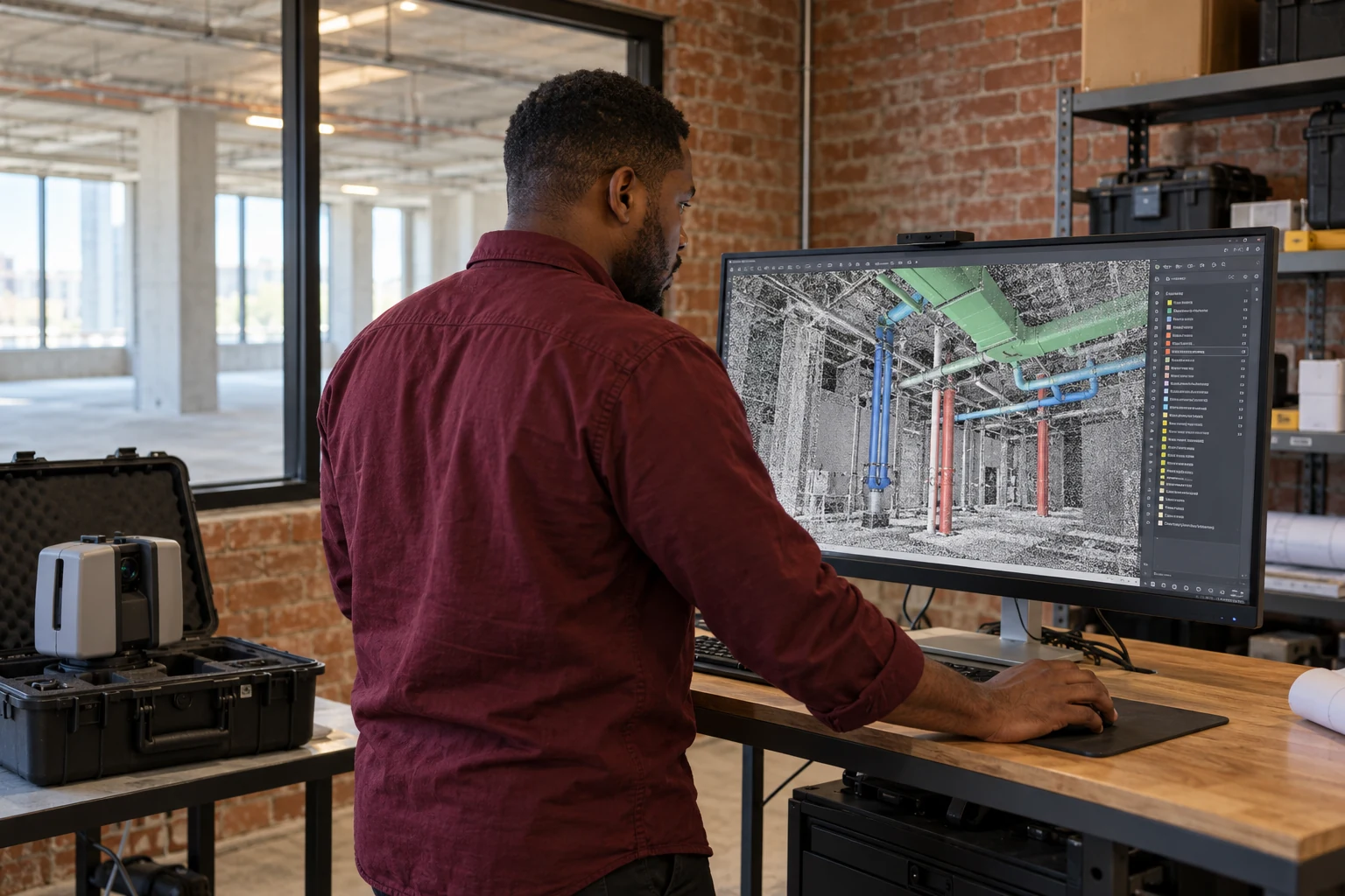
3D laser scanning MEP clash detection improves coordination by giving designers a measured model of existing ceilings, shafts, and mechanical rooms to test new systems against before construction. Conflicts surface in software instead of in the field. Plansrow provides 3D laser scanning and Revit BIM modeling of existing MEP for coordination.
3D laser scanning MEP clash detection works by modeling existing conditions from scan data and testing new design models against them in coordination software. Crews scan the spaces where new systems will run, such as ceiling plenums, shafts, and mechanical rooms, capturing existing ducts, pipes, conduit, beams, and hangers. Modelers then build those existing elements in Revit at an agreed LOD, often LOD 300 or LOD 350 in tight zones. The existing conditions model and the new design models are combined in a coordination tool such as Autodesk Navisworks, where Clash Detective runs automated tests. Many teams also load the point cloud itself as a reference to check unmodeled obstructions. The result is a list of conflicts that designers can resolve before trades mobilize.
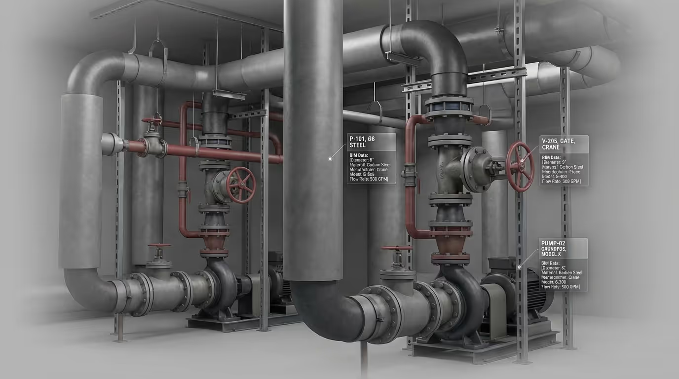
A hard clash is a physical intersection between two objects, while a clearance clash, often called a soft clash, flags objects that come within a specified distance of each other. In Navisworks Clash Detective, the default test types are Hard, Hard (Conservative), Clearance, and Duplicates. Hard tests catch a new duct passing through an existing beam. Clearance tests catch problems that are not intersections but still cause field issues, such as missing space for pipe insulation, maintenance access, or required separation between systems. Duplicate tests find geometry modeled twice. Running clearance tests against a scanned existing conditions model is especially useful in renovations, where small tolerances around old structure often decide whether a new system fits.
Scan every space where new MEP systems will run or connect, with the most attention on congested ceiling plenums, vertical shafts, and mechanical and electrical rooms. In many San Francisco commercial buildings, decades of tenant improvements have left abandoned ductwork, rerouted pipes, and added conduit that archived drawings do not show. Ceiling tiles may need to be removed in sections so the scanner can see above them. Structural elements matter as much as MEP, because beam depths, slab penetrations, and seismic bracing often limit routing options. Roofs with existing equipment and points of connection to utilities should also be included. Plansrow's as-built documentation services can capture these areas and deliver MEP routing drawings or models.
Scan-based clash detection reduces RFIs because conflicts with existing conditions are resolved in the model before contractors discover them in the field. When designers route new systems against measured geometry rather than assumed dimensions, fewer field questions arise about obstructions, elevations, or clearances. Measured existing conditions also make prefabrication more practical. Fabricators can build duct, pipe, and multi-trade racks offsite with greater confidence that assemblies will fit, which supports cleaner installation in occupied buildings. Timing matters: scanning before design development gives engineers accurate constraints, and a second scan before ceilings close in can confirm that installed work matches the coordinated model. Our guide to converting a point cloud to a Revit BIM model explains how existing MEP is modeled accurately.
Plansrow provides 3D laser scanning and existing MEP modeling for clash detection in San Francisco, with hubs in San Diego, Fresno, Austin, Baltimore, and Seattle serving AEC firms nationwide. The team has more than 15 years of experience and has documented more than 3 million square feet. Crews capture with Leica scanners and Matterport, process data in Autodesk software, and deliver point clouds, as-built CAD drawings with MEP routing, and Revit models at LOD 200 to LOD 400 for coordination. Engineers and contractors can bring those deliverables directly into their coordination workflows, and scope can be limited to the floors, shafts, or mechanical rooms where new systems will run. To scope scanning for your next MEP project, request an instant online quote.
By subscribing, you agree to our Privacy Policy and consent to receive updates from our company.
